
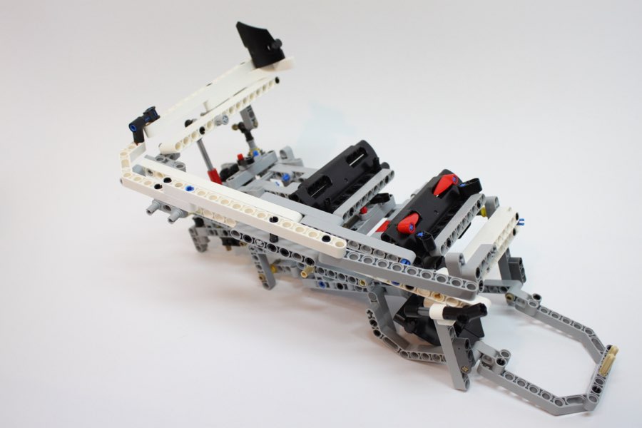
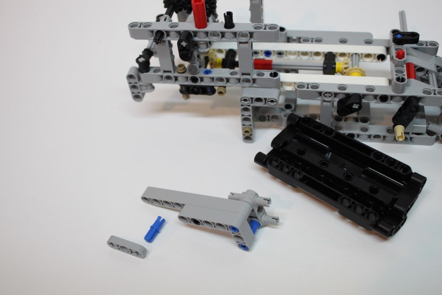
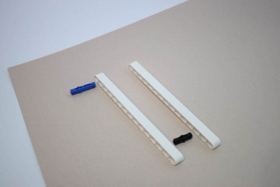
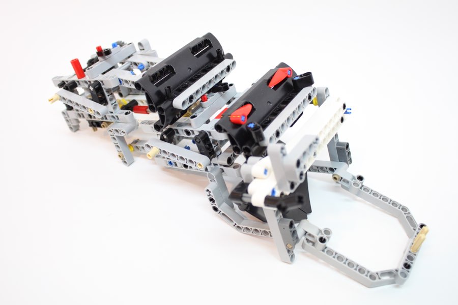
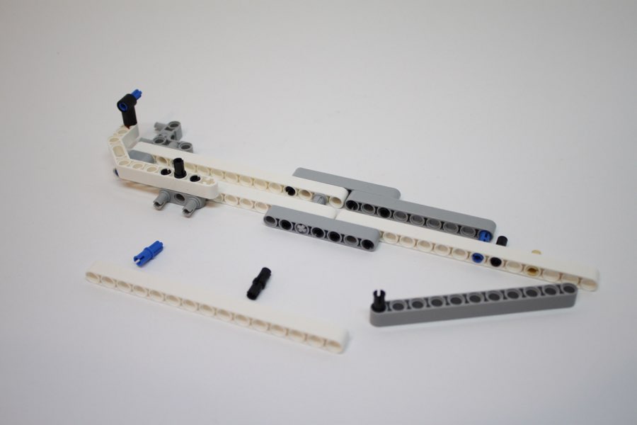
Using the instructions below, try building the Ball Contraption.
If something is not clear, please ask Mr. Kulzer.
2
3
4
5
6
7
8
9
10
11
12
13
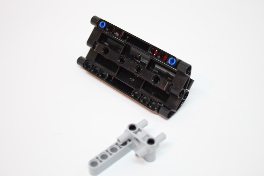
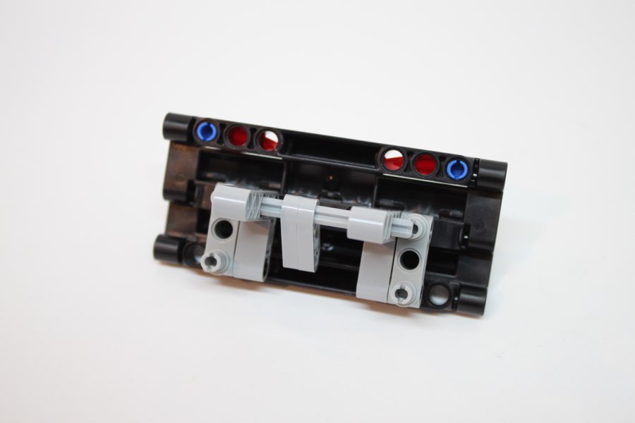
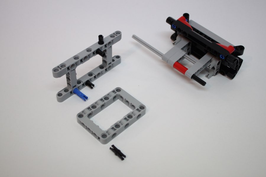
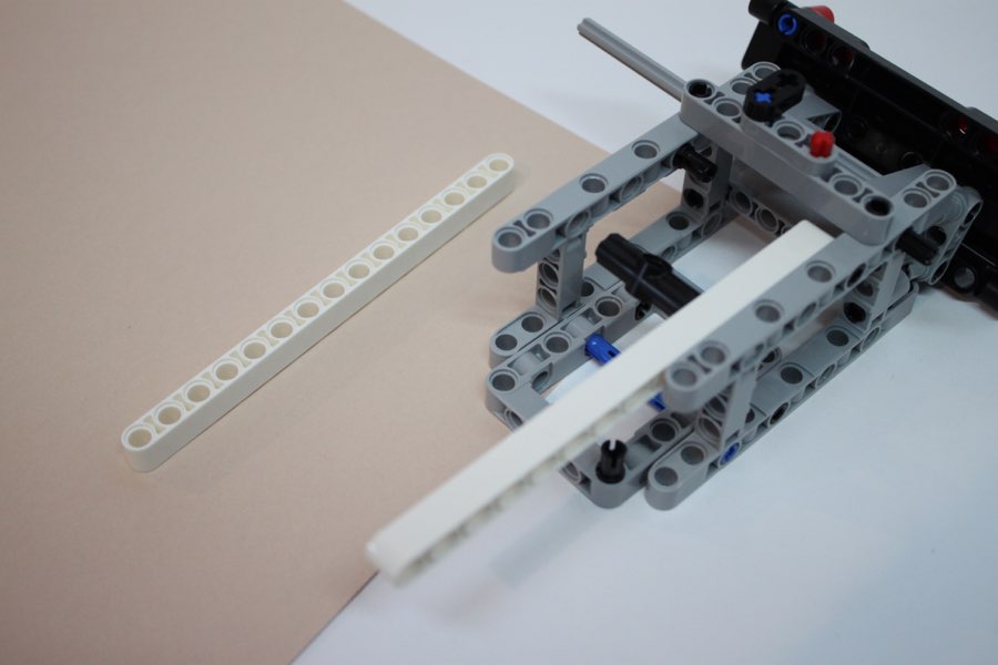
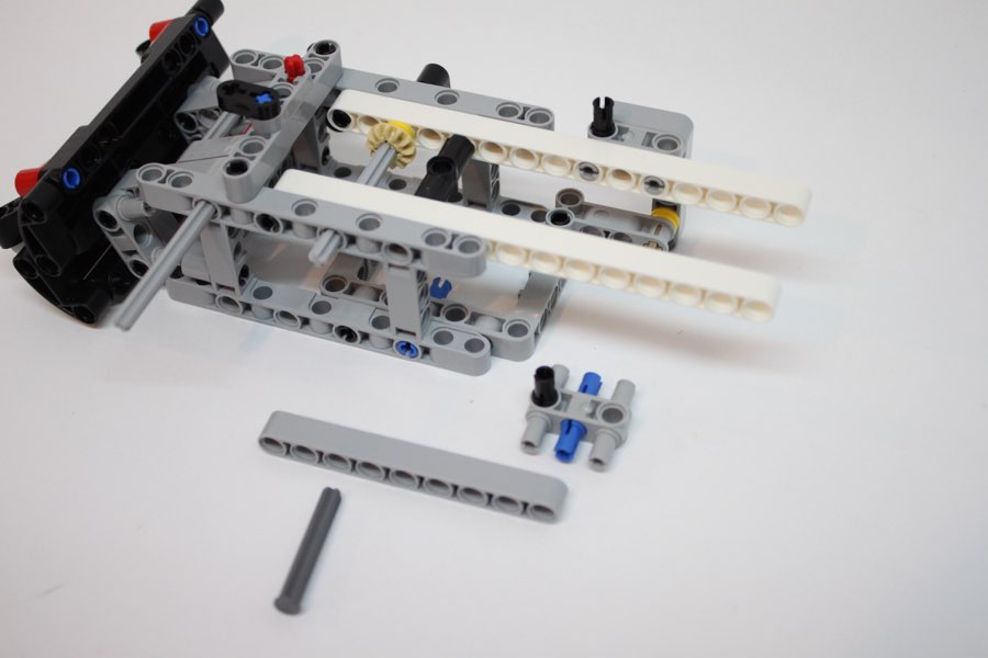
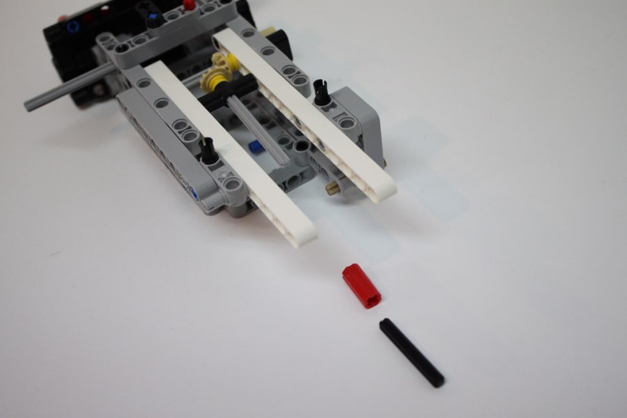
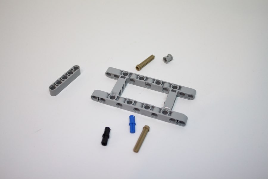
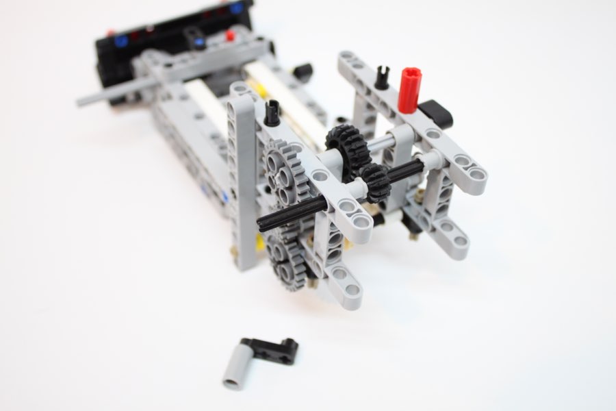
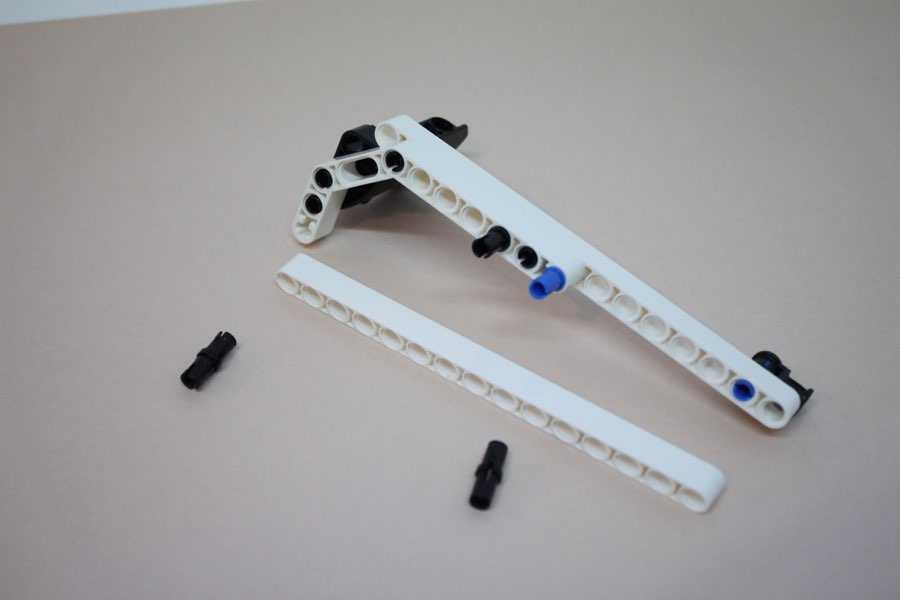
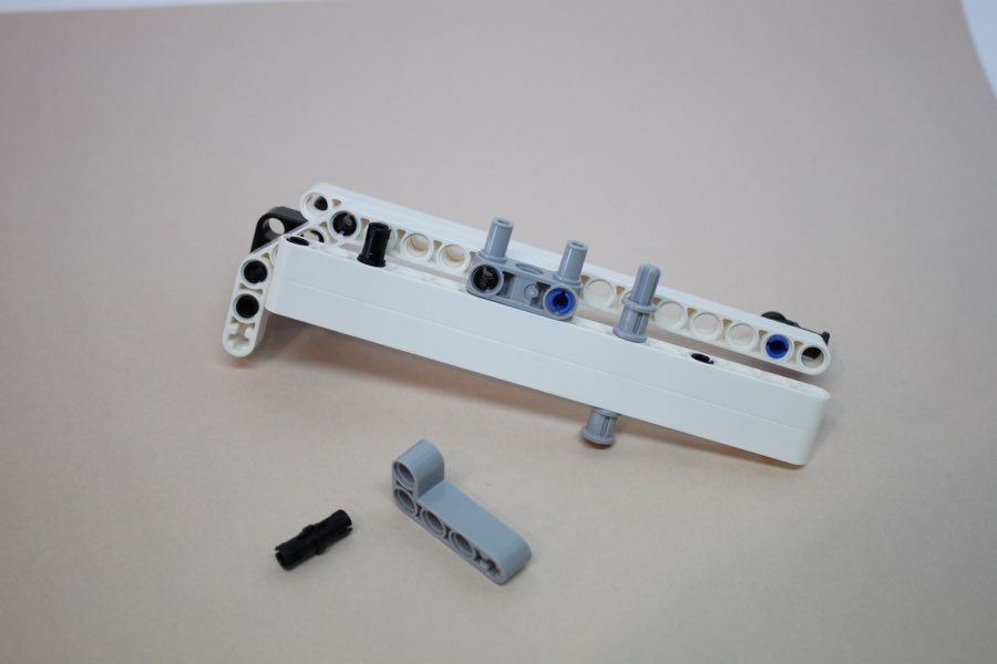
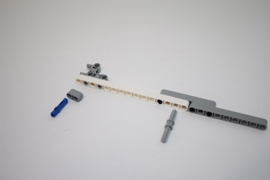
#5 gray axle
14
15
16
17
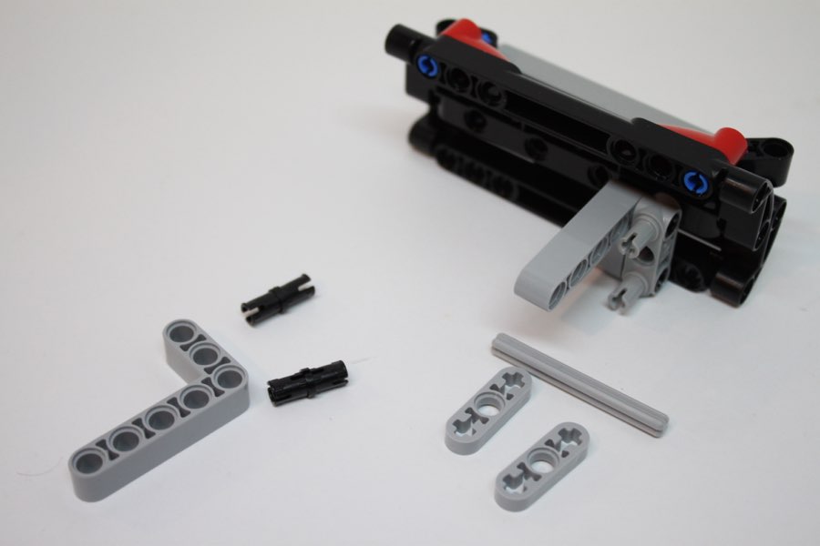
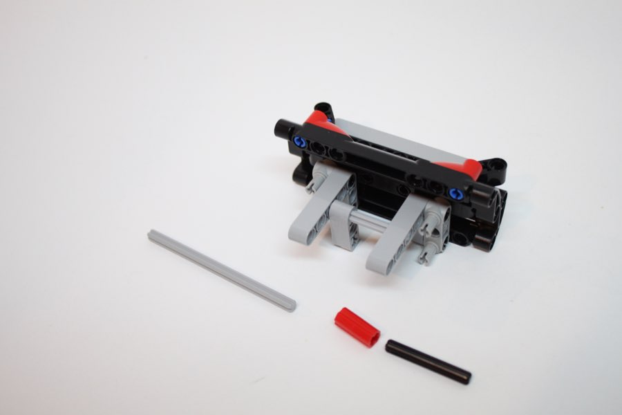
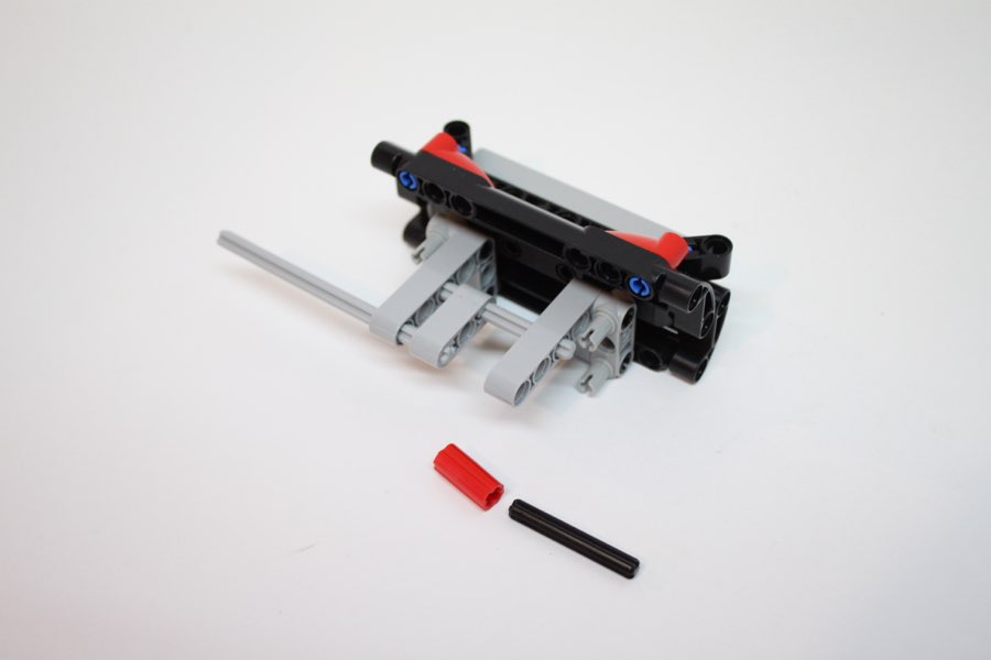
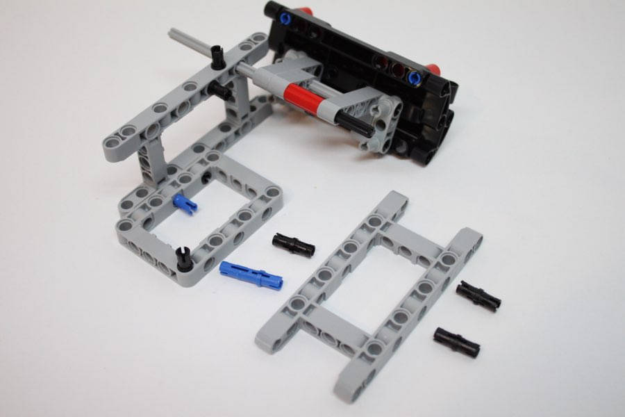
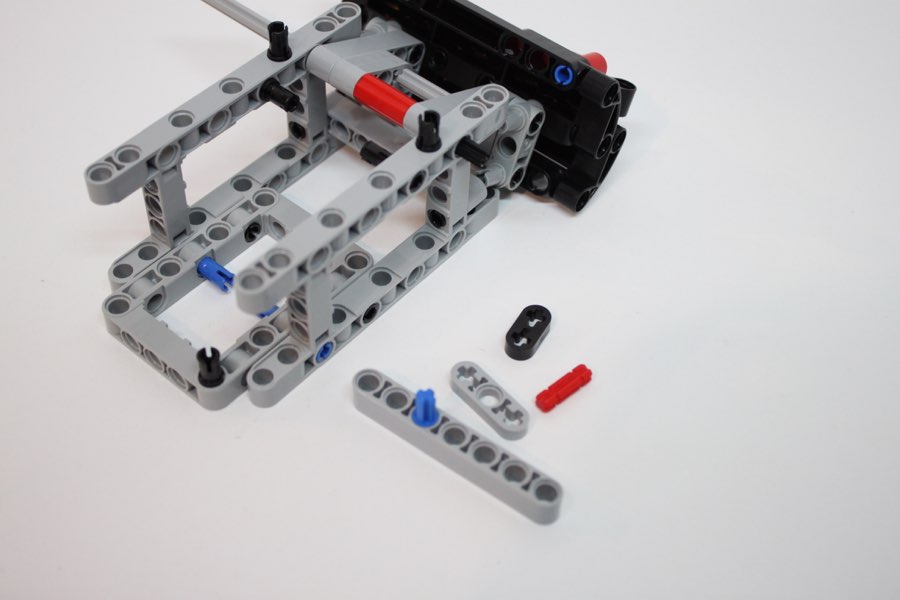
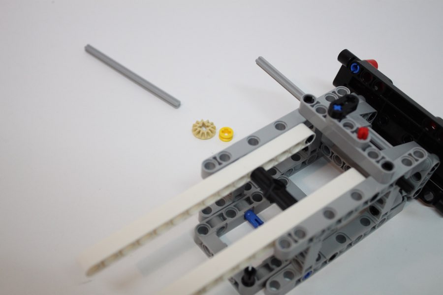
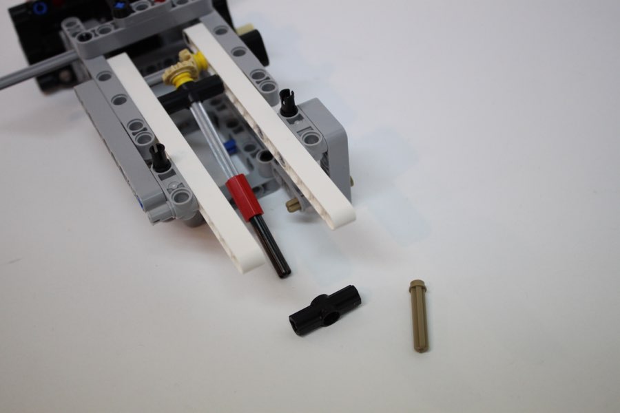
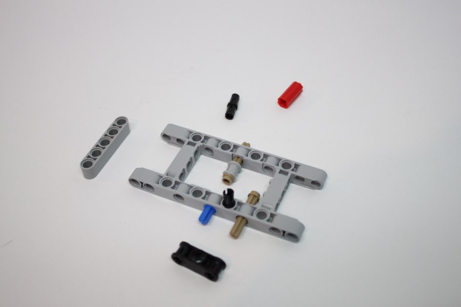
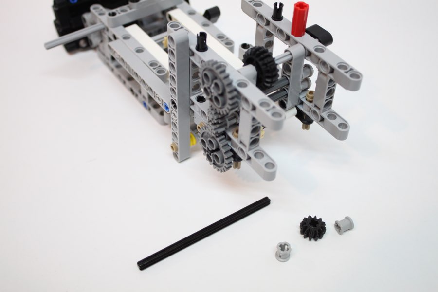
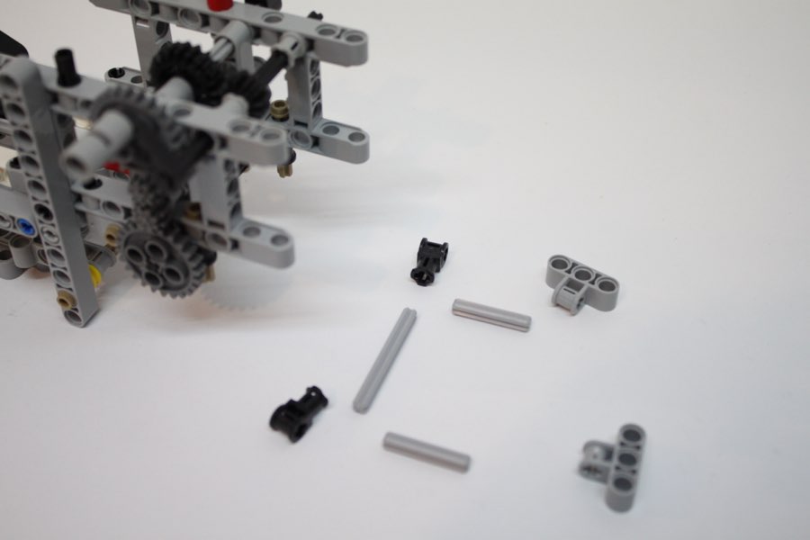
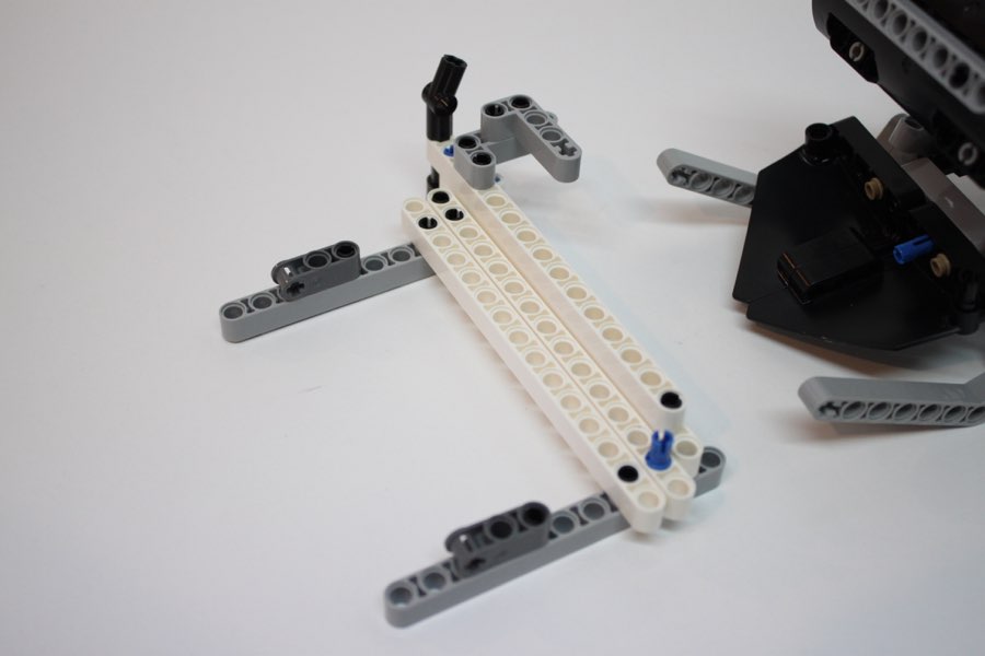
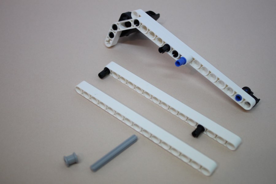
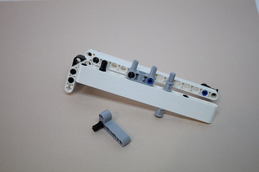
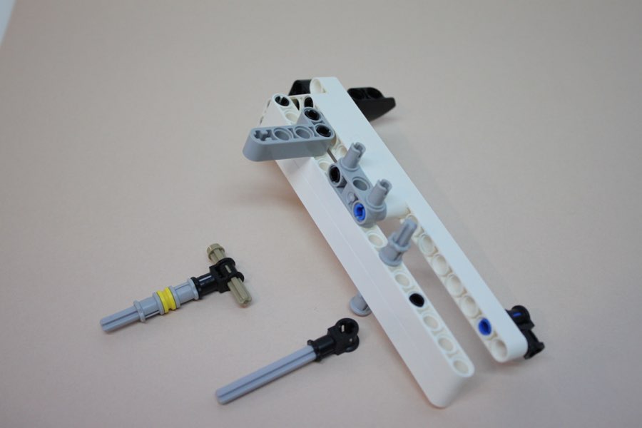
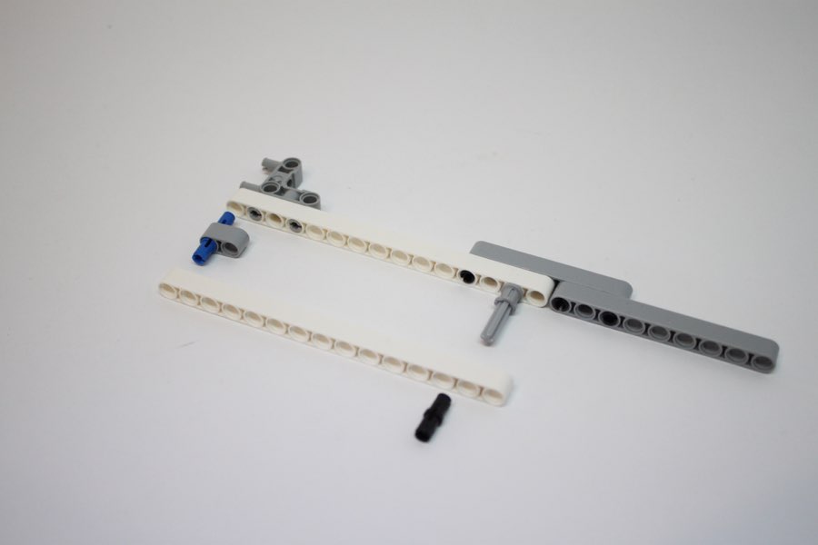
#9 gray axle, #4 black axle
18
19
20
21
22
23
24
25
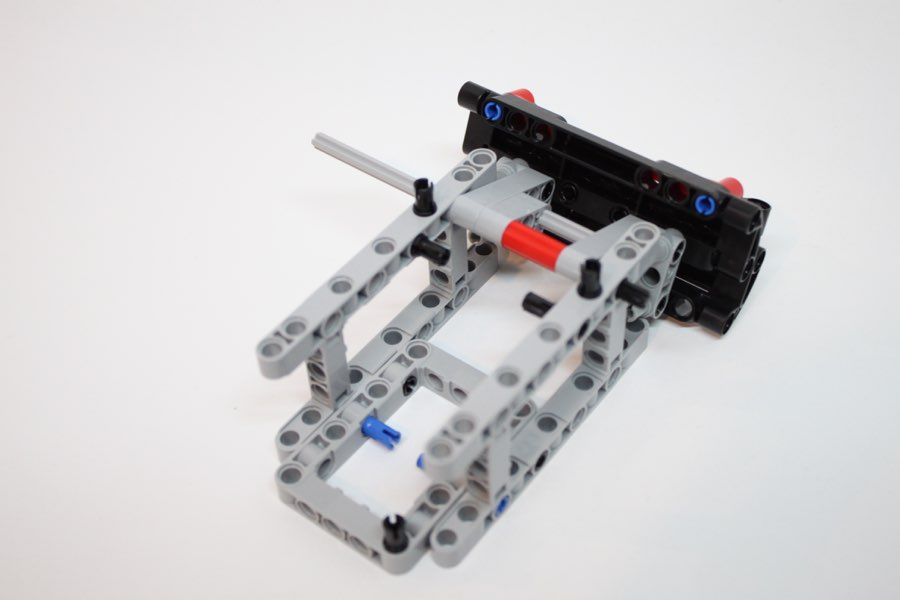
Turn the construction around and flip the lift up.
26
27
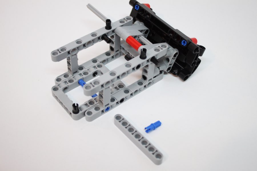
Return the construction to it's original orientation.
28
29
30
31
32
33
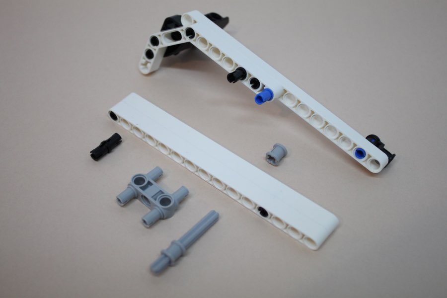
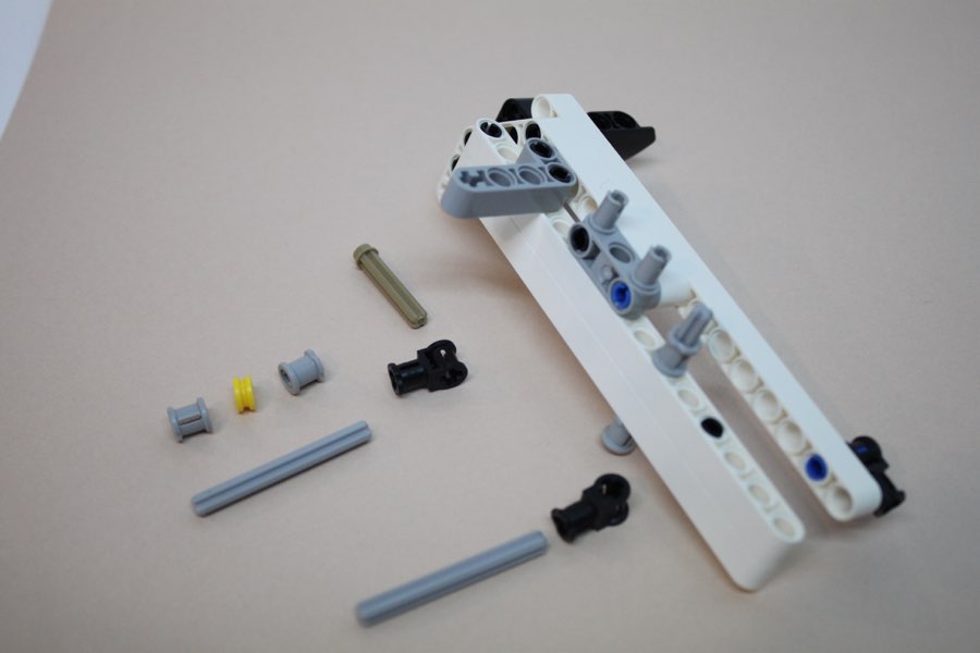
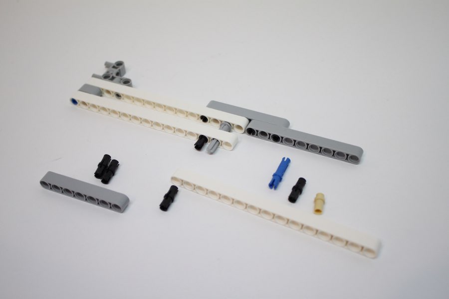
# 9 gray axle
34
35
36
37
38
39
40
41
42
43
44
45
46
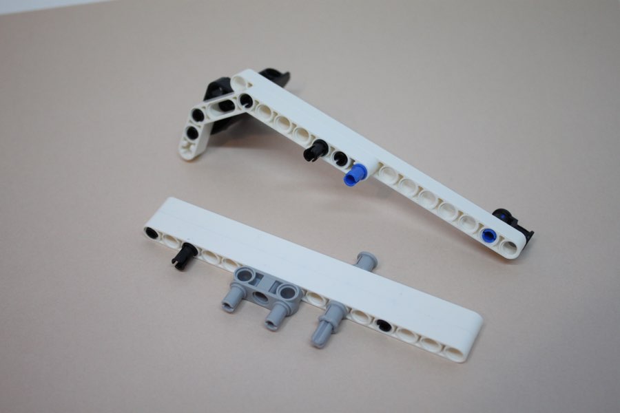
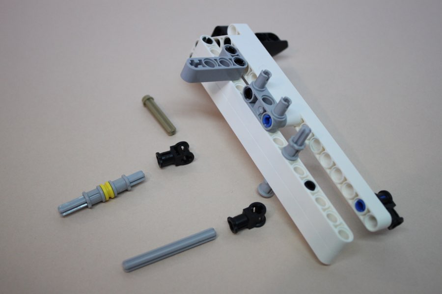
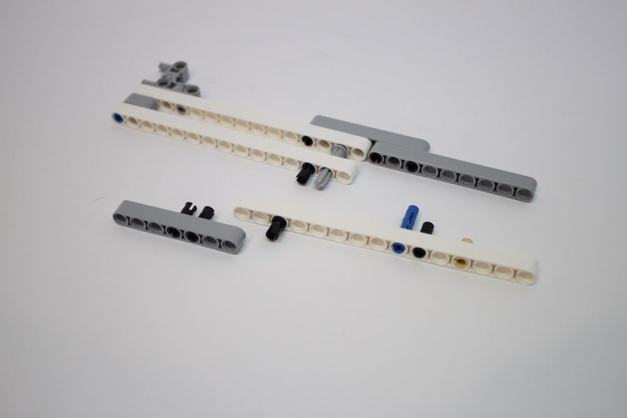
# 7 gray axle
47
48
49
# 4 black axle
50
51
52
53
54
55
56
57
58
59
# 8 black axle
60
61
62
63
64
65
66
67
70
71
72
73
74
75
76
77
78
79
80
81
82
83
# 9 gray axle
84
85
86
87
# 12 black axle
88
89
90
91
92
93
94
# 5 and # 3 gray axles
95
96
97
98
99
100
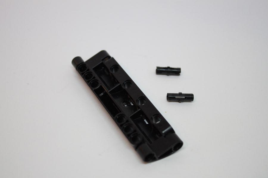
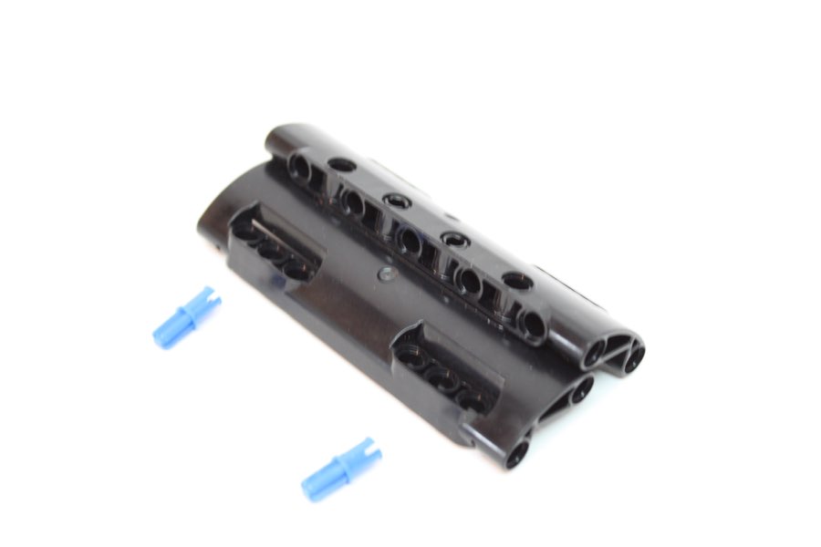
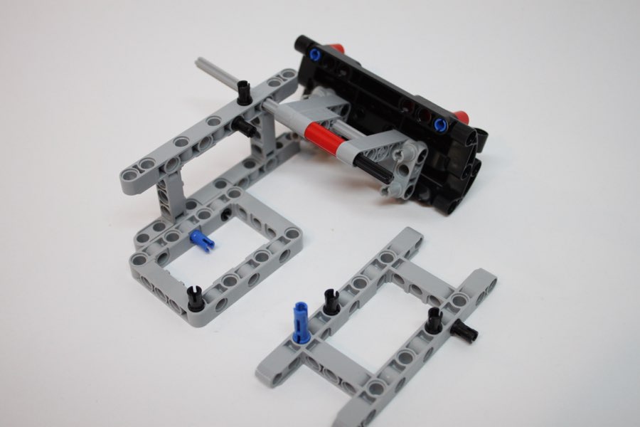
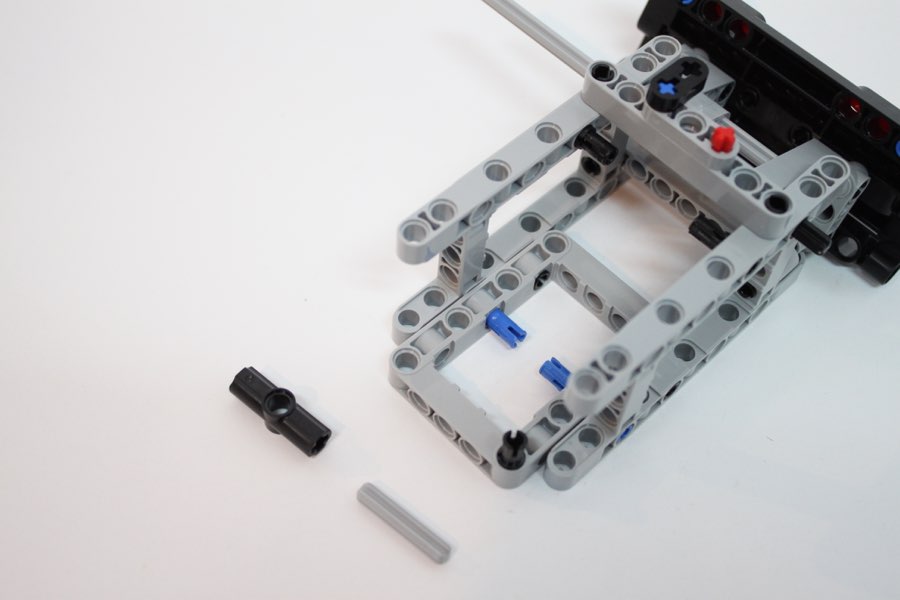
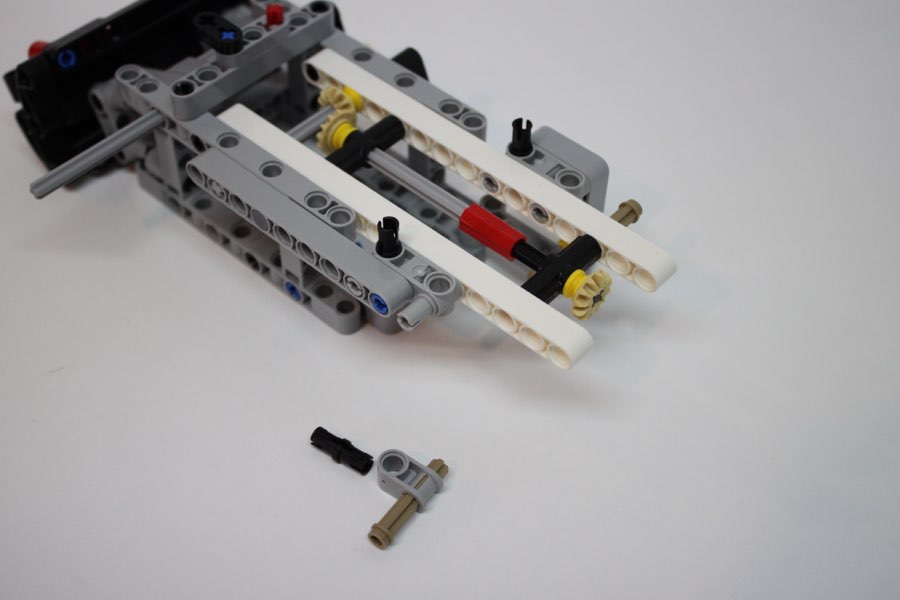
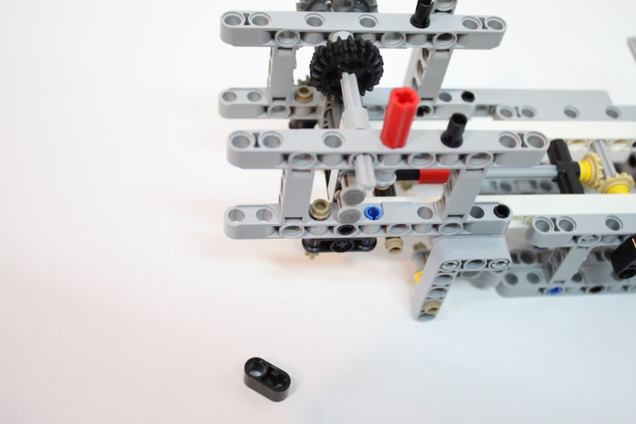
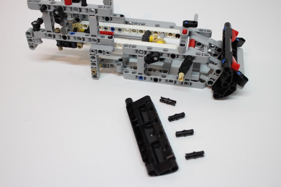
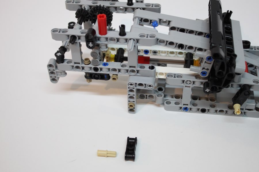
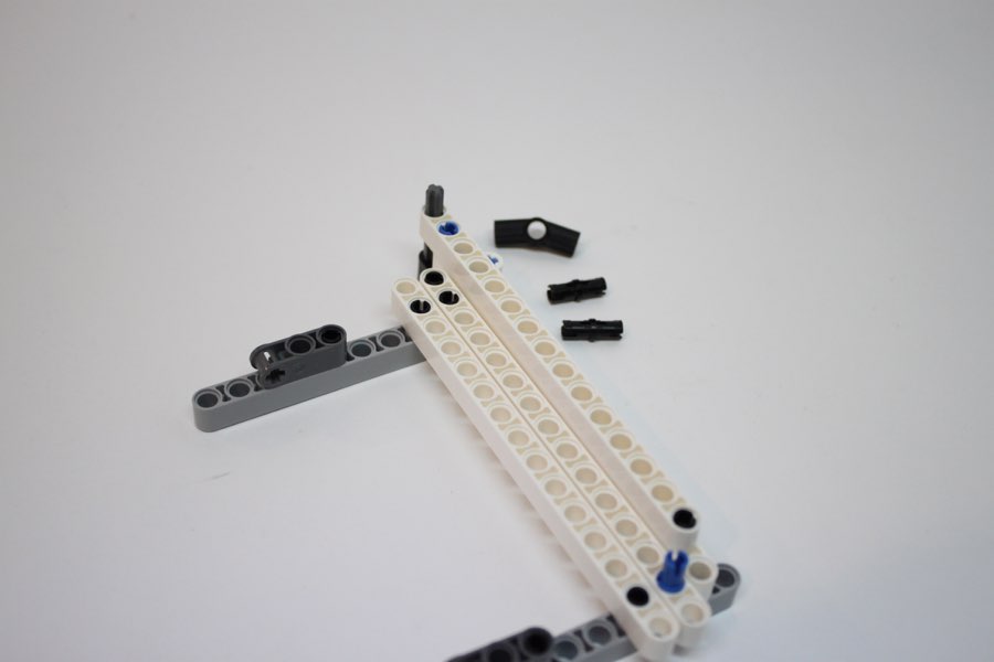
Note where the black pins are inserted
101
102
103
104
105
106
107
108
109
110
111
# 9 gray axle
112
113
114
115
116
117
118
119
120
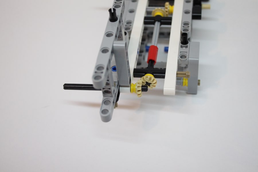
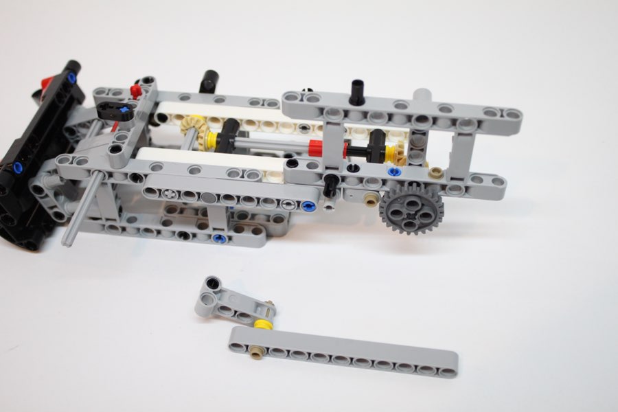
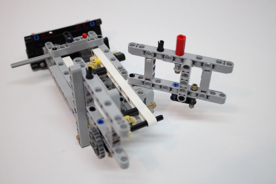
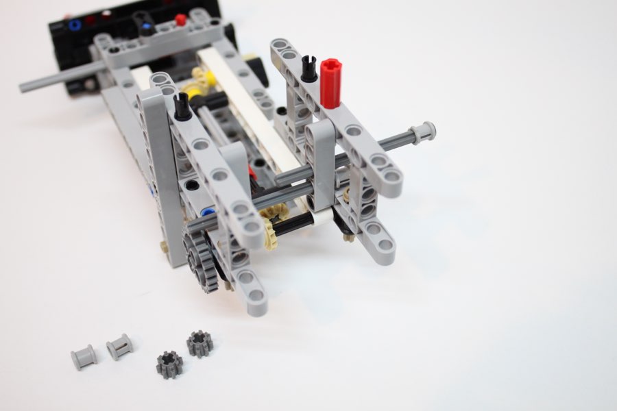
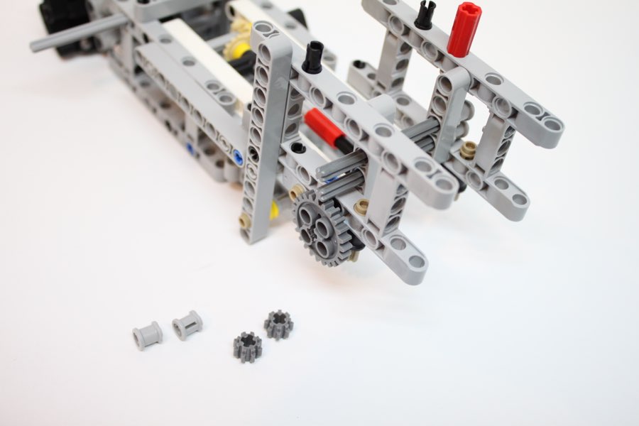
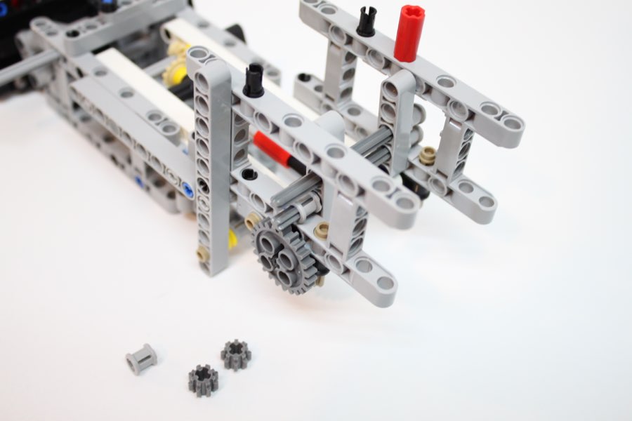
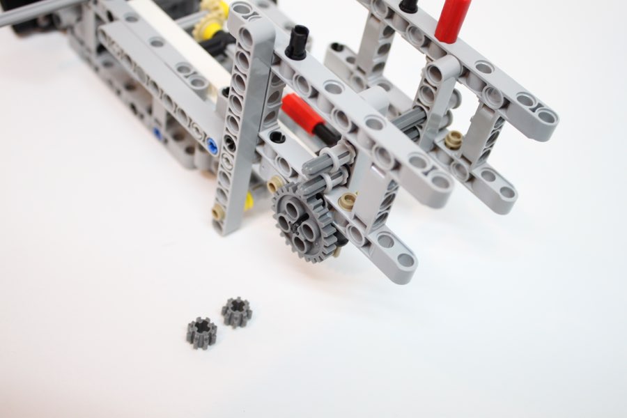
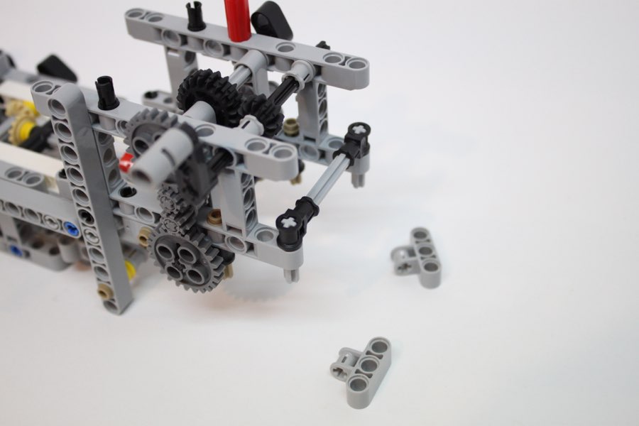
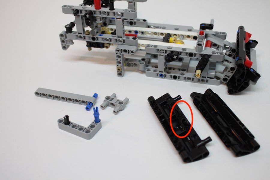
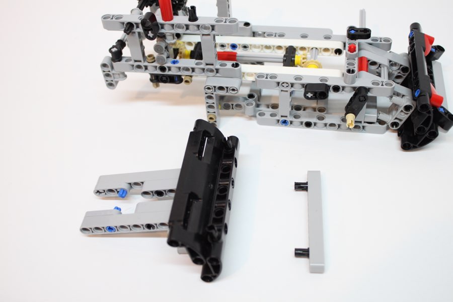
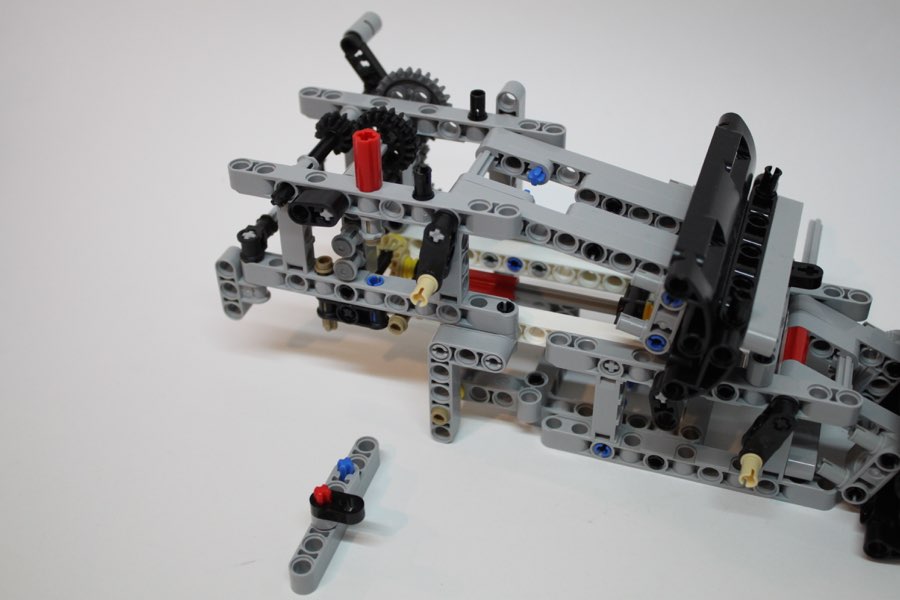
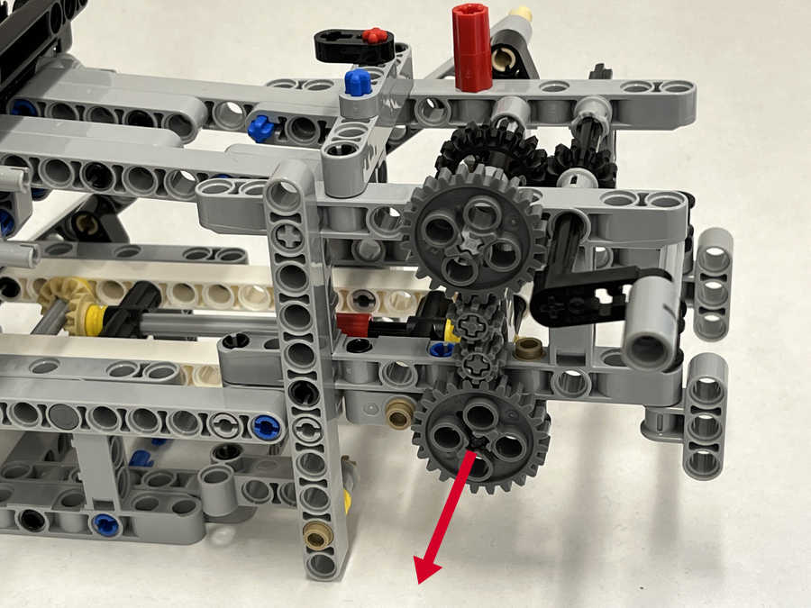
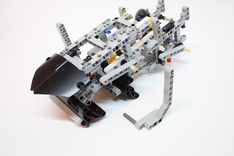
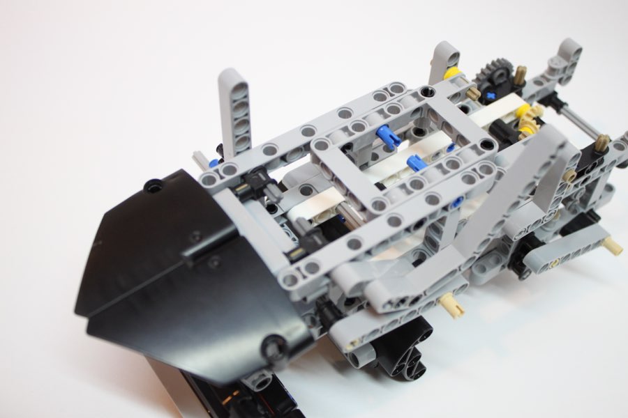
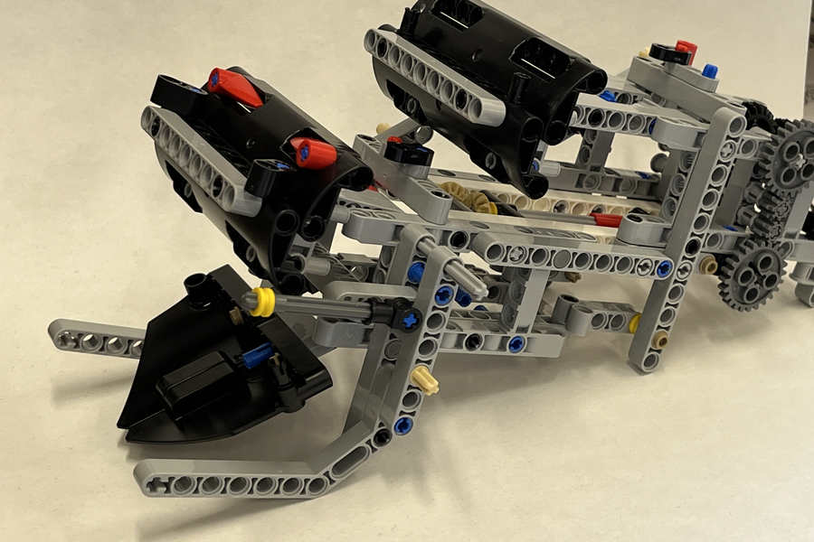
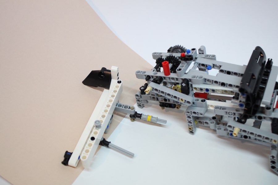
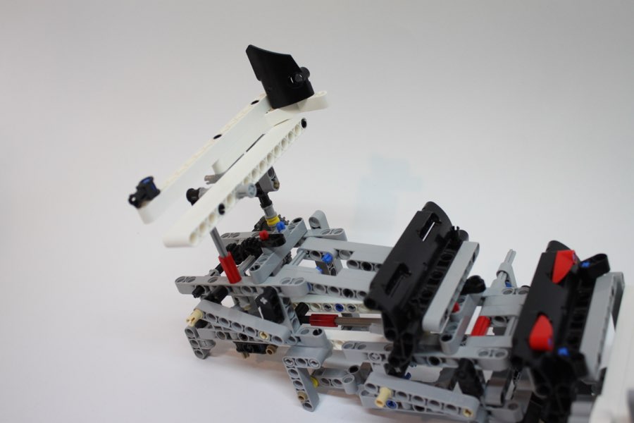
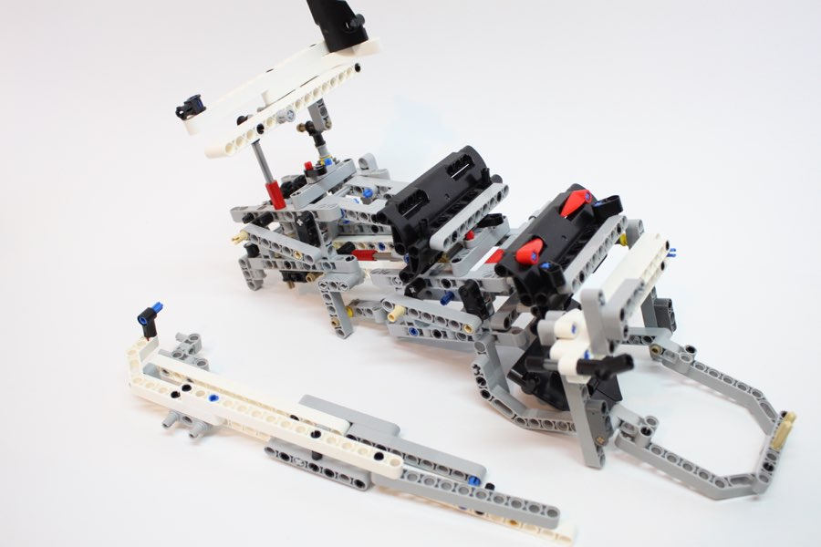
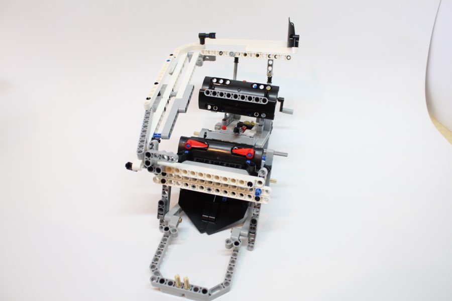
Note the angle of each part connecting the beam you added. Please make sure it looks like this picture.
121
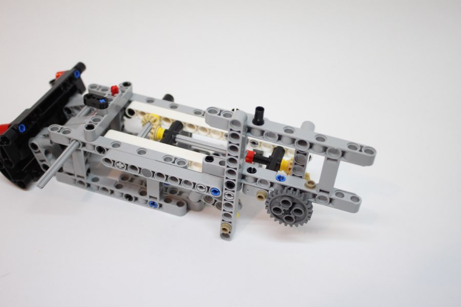
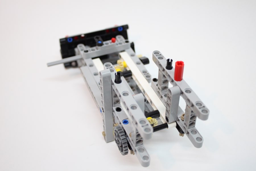
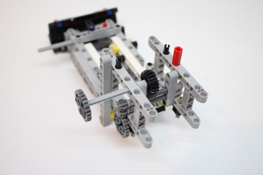
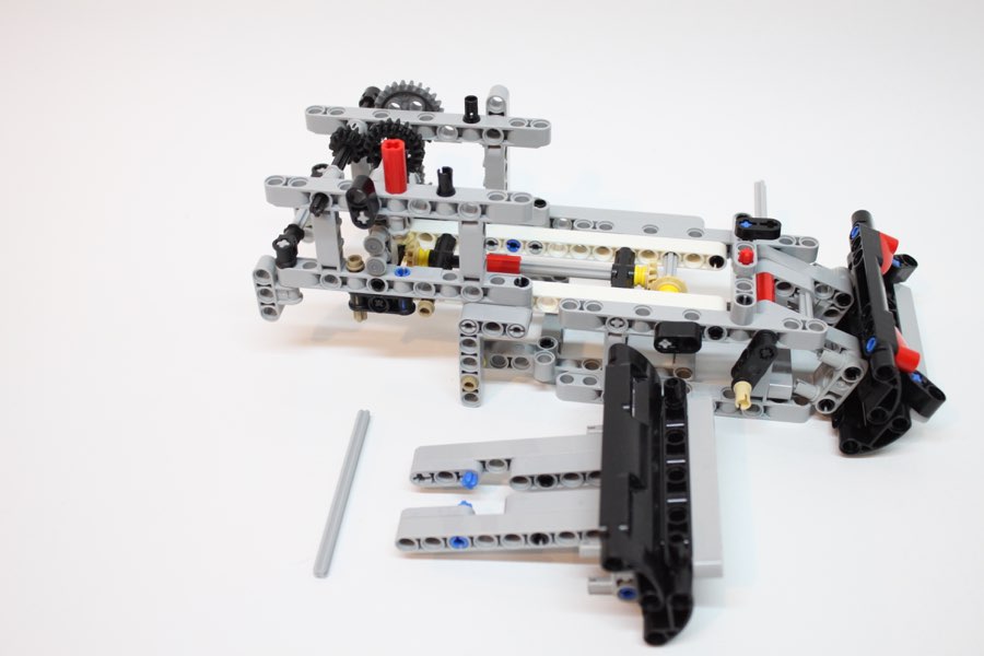
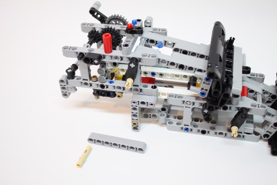
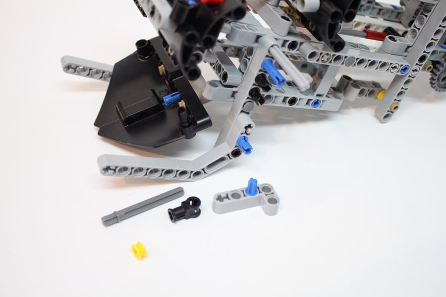
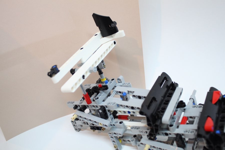
Note the angle of the lift levers in this picture. The angle/timing of the lift levers is critical.
121b
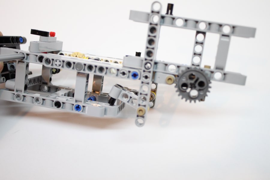
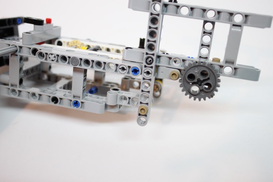
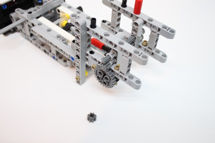
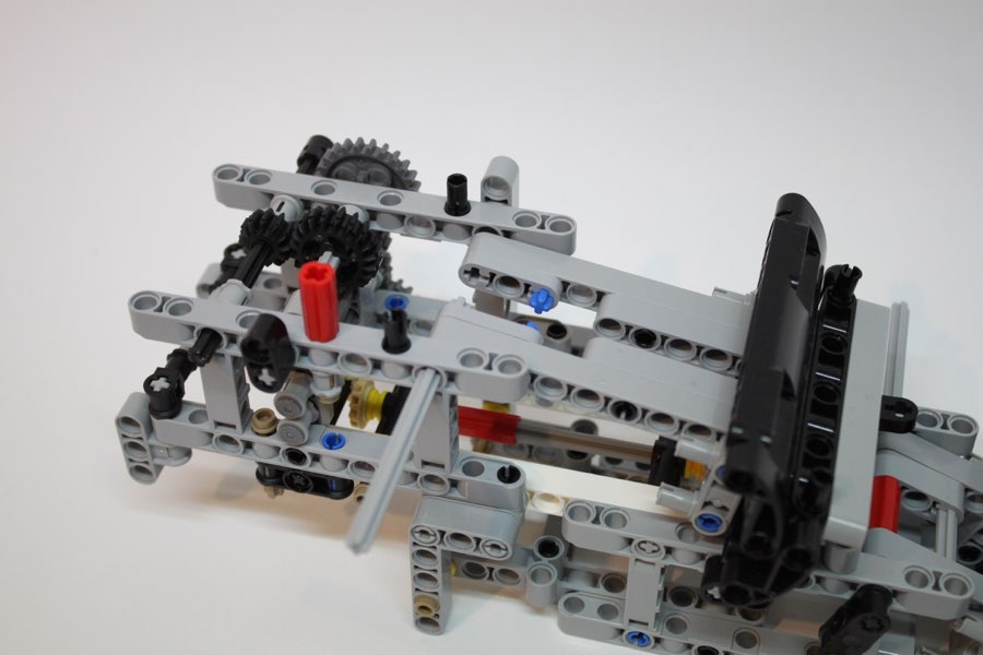
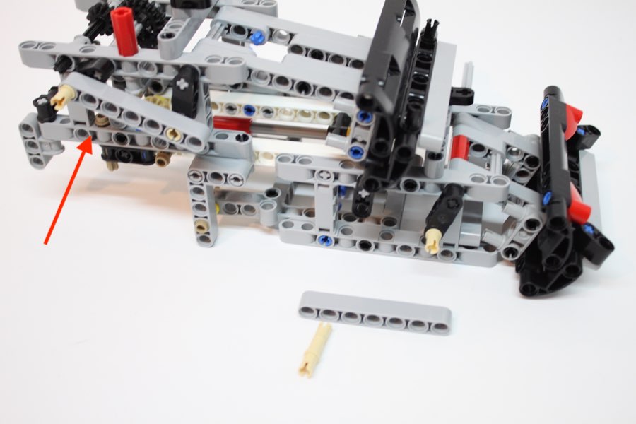
To adjust the angle of the lift levers, pull the #24 gear out (See red arrow) until the others can be adjusted, then push it back in.
122
123
124
125
126
127
Flip the whole assembly upside-down.
128
129
130
131
132
133
134
135
Flip the whole assembly rightside-up again.
136
137
138
139
139b
140
141
142
143
144
145
146
147
148
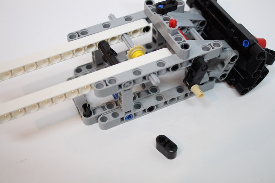
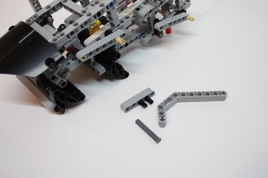
Use a #3 black angle connector.
149
150
151
152
153
Flip this assembly over.
154
155
156
157
158
159
160
161
162
163
164
165
#5 gray axle
166
167
168
169
Back to top
170
171
#5 gray axles
172
173
174
175
176
177
178
179
# 5 gray axle
180
181
182
183
184
185
186
187
188
189
190
191
192
Back to top